

-
Products
Overview Products

-
2D Cutting
-
Tube Cutting
-
3D Cutting
-
Intelligent Welding
-
Intelligent Cutting Head
-
Industrial Automation
-
Industrial Software
-
Combination
Controller
-
Combination
BOCHU New Product -
Combination
BOCHU New Product -
Controller
BOCHU New Product -
2D Cutting Head
Tube Cutting Head
3D Cutting Head
BOCHU New Product -
BOCHU New Product
-
- Support
- About
- Online Store


品頁規(guī)格型號.png)


- Software Download
- Manual
- Video
- Tutorial
-
- Tubest-The Layer Mapping
- Tubest-In-part shape(Nested Contours)
- TubesT - Auto Add Text
- TubesT - Quick Rectangle Path
- TubesT - Save the YXY File
- Tubest- Auto Backup
-
-
-
-
TubesT - Adding an Intersect Hole on Grooves Aligned with Cut-Off Lines
I. Introduction
When a long, narrow groove on the end face is designed to allow a plate to be inserted, the groove walls are required to be vertical. In such cases, 【Intersect Hole】process is needed. However, these grooves are often connected to the end face, making it difficult to apply the intersect hole process separately.
So how can we quickly isolate the groove from the end face and independently apply the intersecting hole process to it? This article provides a detailed explanation.
Ⅱ. How to use
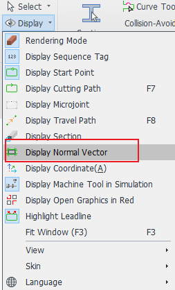
1. Display the normal vectors to check whether the groove requires an intersect hole.
If the groove's vector already aligns with the pink section, then the intersect hole process is not necessary.

2. Use 【Set Close Up End】 to separate the groove from the cut-off line.
In most cases, no inward offset is needed, so there's no need to check the option "Close Groove/Slot Closure". Simply set the application range and click "OK".
If you want to learn more about this function, you can click the link in the subheading to jump to the related tutorial.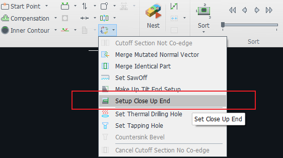
Note:The default layout is slightly different between the Steel Structure and Pro versions.
?
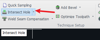
3. Select the separated grooves and click 【Intersect Hole】.
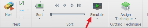
Be sure to check the normal vectors or do a simulation after setting to see if the cutting head is swinging at the desired angle.
4. Select the slot where the Intersect hole is set and change the layer colour (optional).
The purpose of changing the layer is to change the set of machining parameters for better cutting.
If the actual cutting of Intersect holes and ordinary follow cutting process parameters are the same, but the results are not ideal, you can distinguish between the colours, so that different ways to cut with different process parameters.
Ⅲ. FAQS
1. How to apply the Intersecting Hole process to only a small section of a groove?
Refer to the tutorial: "TubesT – Add Different Layers for a Single Cutting Path".
For example, you can apply the Intersecting Hole process only to the arc segment (from point 2 to point 3 in the right image).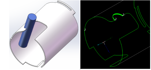
?
2. What if you're using a version of TubesT earlier than 1.57 and don't have the 【Set Close Up End】 function?
You can either upgrade the software, or manually split the profile. Refer to the tutorial below:
-
-
-
Avoid placing the split point at corners
-
Use Curve Split
-
Apply the Intersect Hole process to each segment separately
(Change the layer to use a different set of cutting parameters for better results) -
Merge connected lines after setting the process
-
-
-
-
-
-
-
-
-
Avoid placing the split point at corners
-
Use Curve Split
-
Apply the Intersect Hole process to each segment separately
(Change the layer to use a different set of cutting parameters for better results) -
Merge connected lines after setting the process
-
-
TubesT - Adding an Intersect Hole on Grooves Aligned with Cut-Off Lines 1750viewI. Introduction
When a long, narrow groove on the end face is designed to allow a plate to be inserted, the groove walls are required to be vertical. In such cases, 【Intersect Hole】process is needed. However, these grooves are often connected to the end face, making it difficult to apply the intersect hole process separately.
So how can we quickly isolate the groove from the end face and independently apply the intersecting hole process to it? This article provides a detailed explanation.
Ⅱ. How to use
1. Display the normal vectors to check whether the groove requires an intersect hole.
If the groove's vector already aligns with the pink section, then the intersect hole process is not necessary.
2. Use 【Set Close Up End】 to separate the groove from the cut-off line.
In most cases, no inward offset is needed, so there's no need to check the option "Close Groove/Slot Closure". Simply set the application range and click "OK".
If you want to learn more about this function, you can click the link in the subheading to jump to the related tutorial.Note:The default layout is slightly different between the Steel Structure and Pro versions.
?
3. Select the separated grooves and click 【Intersect Hole】.
Be sure to check the normal vectors or do a simulation after setting to see if the cutting head is swinging at the desired angle.
4. Select the slot where the Intersect hole is set and change the layer colour (optional).
The purpose of changing the layer is to change the set of machining parameters for better cutting.
If the actual cutting of Intersect holes and ordinary follow cutting process parameters are the same, but the results are not ideal, you can distinguish between the colours, so that different ways to cut with different process parameters.
Ⅲ. FAQS
1. How to apply the Intersecting Hole process to only a small section of a groove?
Refer to the tutorial: "TubesT – Add Different Layers for a Single Cutting Path".
For example, you can apply the Intersecting Hole process only to the arc segment (from point 2 to point 3 in the right image).?
2. What if you're using a version of TubesT earlier than 1.57 and don't have the 【Set Close Up End】 function?
You can either upgrade the software, or manually split the profile. Refer to the tutorial below:


