

-
Products
Overview Products

-
2D Cutting
-
Tube Cutting
-
3D Cutting
-
Intelligent Welding
-
Intelligent Cutting Head
-
Industrial Automation
-
Industrial Software
-
Combination
-
Combination
BOCHU New Product -
Combination
BOCHU New Product -
Controller
BOCHU New Product -
2D Cutting Head
Tube Cutting Head
3D Cutting Head
Consumables
BOCHU New Product -
Servo
BOCHU New Product -
Industrial 4.0
-
- Support
- About
- Online Store


品列表圖片_514x337.png)


品頁規(guī)格型號.png)

品列表.png)


- Software Download
- Manual
- Video
- Tutorial
- TubesT - The version of TubesT corresponding to TubePro
- TubesT - How to Get Free Small Tube Edition of TubesT
-
- TubesT - The Solution for Machining of Sheet Metal Parts
- TubesT - The Solution for Machining of Shaped Tube
-
- TubesT - The Layer Mapping
- TubesT - In-part shape(Nested Contours)
- TubesT - Create Part by Excel Table
- TubesT - Part Drawing- Marking
- TubesT - Start Point
- TubesT - Intersect Hole
- TubesT - Tutorial on Toolpaths for Processing Sheet Metal Parts
- TubesT - Microjoint
- TubesT - Merge as I-Beam
- TubesT- Rotate Section
- TubesT - Add Text
- TubesT - Auto Add Text
- TubesT - Batch Add Text
- TubesT - Quick Rectangle Path
- TubesT - Make Up Tilt End
- TubesT - Close Up End
- TubesT - Nudge Graphic
- TubesT - Merge Parts
- TubesT - Manual Nest
- TubesT - Parts Combination
- TubesT - Sort
- TubesT - Manual Sort
- TubesT - Simulate
- TubesT - Cloud Based (Online)Laser Cutting Heads
- TubesT - Save the YXY File
- TubesT - Auto Backup
- Tubest - Use File Name for Imported Parts
- TubesT - Cloud Parts Library
-
- TubesT - How to choose the scope of application?
- TubesT - How to mark
- TubesT - Tutorial on Toolpaths for Processing Sheet Metal Parts
- TubesT - Custom Profile Toolpath Contour for Shaped Tube
- TubesT - How to set up double-sided cutting for the web of an I-beam
- Tubest - Modifying Drawings for Curved Bevels on I-Beams
-
TubesT - Auto Technique
Ⅰ. Overview
?
If you are already familiar with certain technique configurations in TubesT, or the fixed technique parameters are used in your production, the Auto Technique feature can be enabled before importing parts. Once configured, the software will automatically add techniques to each part during import, eliminating the need for manual configuration afterward. Check the added techniques after import.
Ⅱ. Instructions
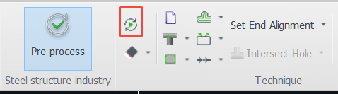
(1) Click Auto Technique and enable the required technique options.
(2) Import the parts and review the automatically added techniques.
※Notice: If parts have already been imported before enabling Auto Technique, only parts imported after activation will be applied the added techniques. Previously imported parts will not be applied the techniques automatically.
Ⅲ. Additional Notes?
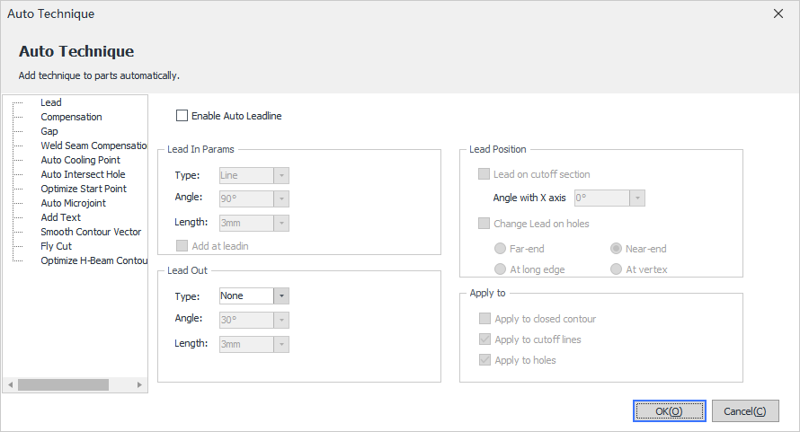
(1) Lead: Lead on the Auto Technique page refers to standard Lead Line only. For more descriptions, please refer to?Lead Line tutorial.?
(2) Compensation: Compensation on the Auto Technique page refers to standard kerf compensation. For more descriptions, please refer to Compensation?tutorial.?
-
-
- For fixed height compensation, please refer to the ?Kerf Compensation (fixed height) tutorial.
-
(3) Gap: For more descriptions, please refer to? Gap ?tutorial.
?
(4) Weld Seam Compensation: For more descriptions, please refer to? Weld Seam Compensation tutorial.?
?
(5) Auto Cooling Point: For more descriptions, please refer to?Cooling Point tutorial.?
?
(6) Auto Intersect Hole: For more descriptions, please refer to? Intersect Hole ?tutorial.?
(7) Add Text: For more descriptions, please refer to Add Texttutorial.?
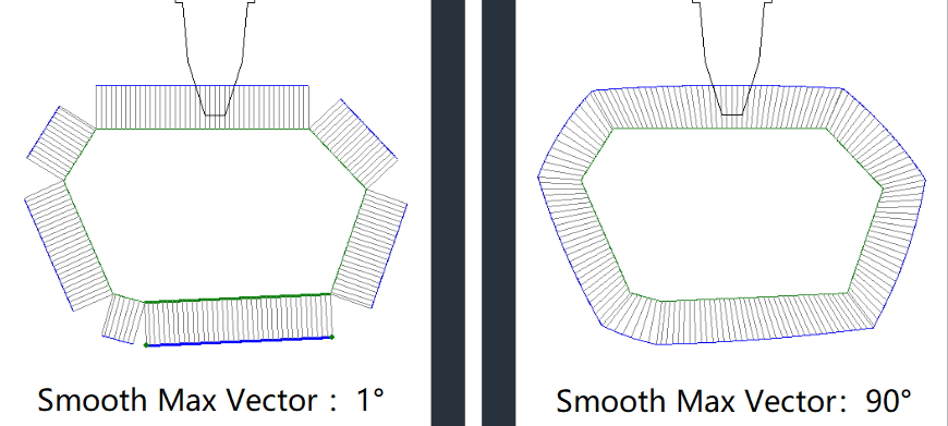
(8) Smooth Contour Vector: Smooth contour vector currently has no tutorial link. This function is mainly used to smooth sharply changed vector.
Max Smooth Angle: In cases where a toolpath on a special-shaped profile has a sudden vector change at a corner, this parameter defines the maximum allowable transition angle.
The configurable range is between 0.1° and 90°.
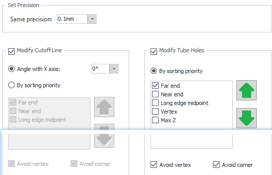
(9) Optimize Start Point:
(10) Fly Cut: For more descriptions, please refer to? Fly Cut? tutorial.?
(11) Optimize H-Beam contour vector: Optimize H-Beam contour vector applies to non-bevel toolpaths using the chc cutting head model. For more descriptions, please refer to Edit Normal Vector of Contours tutorial.
-
-
- For bevel toolpaths, please refer to Collision-Avoid tutorial.
-
-
-
-
- For fixed height compensation, please refer to the ?Kerf Compensation (fixed height) tutorial.
-
-
-
- For bevel toolpaths, please refer to Collision-Avoid tutorial.
-
TubesT - Auto Technique 7375viewⅠ. Overview
?
If you are already familiar with certain technique configurations in TubesT, or the fixed technique parameters are used in your production, the Auto Technique feature can be enabled before importing parts. Once configured, the software will automatically add techniques to each part during import, eliminating the need for manual configuration afterward. Check the added techniques after import.
Ⅱ. Instructions
(1) Click Auto Technique and enable the required technique options.
(2) Import the parts and review the automatically added techniques.
※Notice: If parts have already been imported before enabling Auto Technique, only parts imported after activation will be applied the added techniques. Previously imported parts will not be applied the techniques automatically.
Ⅲ. Additional Notes?
(1) Lead: Lead on the Auto Technique page refers to standard Lead Line only. For more descriptions, please refer to?Lead Line tutorial.?
(2) Compensation: Compensation on the Auto Technique page refers to standard kerf compensation. For more descriptions, please refer to Compensation?tutorial.?
(3) Gap: For more descriptions, please refer to? Gap ?tutorial.
?
(4) Weld Seam Compensation: For more descriptions, please refer to? Weld Seam Compensation tutorial.?
?
(5) Auto Cooling Point: For more descriptions, please refer to?Cooling Point tutorial.?
?
(6) Auto Intersect Hole: For more descriptions, please refer to? Intersect Hole ?tutorial.?
(7) Add Text: For more descriptions, please refer to Add Texttutorial.?
(8) Smooth Contour Vector: Smooth contour vector currently has no tutorial link. This function is mainly used to smooth sharply changed vector.
Max Smooth Angle: In cases where a toolpath on a special-shaped profile has a sudden vector change at a corner, this parameter defines the maximum allowable transition angle.
The configurable range is between 0.1° and 90°.
(9) Optimize Start Point:
(10) Fly Cut: For more descriptions, please refer to? Fly Cut? tutorial.?
(11) Optimize H-Beam contour vector: Optimize H-Beam contour vector applies to non-bevel toolpaths using the chc cutting head model. For more descriptions, please refer to Edit Normal Vector of Contours tutorial.

