

-
Products
Overview Products

-
2D Cutting
-
Tube Cutting
-
3D Cutting
-
Intelligent Welding
-
Intelligent Cutting Head
-
Industrial Automation
-
Industrial Software
-
Combination
-
Combination
BOCHU New Product -
Combination
BOCHU New Product -
Controller
BOCHU New Product -
2D Cutting Head
Tube Cutting Head
3D Cutting Head
Consumables
BOCHU New Product -
Servo
BOCHU New Product -
Industrial 4.0
-
- Support
- About
- Online Store


品列表圖片_514x337.png)


品頁(yè)規(guī)格型號(hào).png)

品列表.png)


-英文.png)

- Software Download
- Manual
- Video
- Tutorial
- TubesT - The version of TubesT corresponding to TubePro
- TubesT - How to Get Free Small Tube Edition of TubesT
-
- TubesT - The Solution for Machining of Sheet Metal Parts
- TubesT - The Solution for Machining of Shaped Tube
-
- TubesT - The Layer Mapping
- TubesT - In-part shape(Nested Contours)
- TubesT - Create Part by Excel Table
- TubesT - Part Drawing- Marking
- TubesT - Start Point
- TubesT - Intersect Hole
- TubesT - Tutorial on Toolpaths for Processing Sheet Metal Parts
- TubesT - Microjoint
- TubesT - Merge as I-Beam
- TubesT- Rotate Section
- TubesT - Add Text
- TubesT - Auto Add Text
- TubesT - Batch Add Text
- TubesT - Quick Rectangle Path
- TubesT - Make Up Tilt End
- TubesT - Close Up End
- TubesT - Nudge Graphic
- TubesT - Merge Parts
- TubesT - Manual Nest
- TubesT - Parts Combination
- TubesT - Sort
- TubesT - Manual Sort
- TubesT - Simulate
- TubesT - Cloud Based (Online)Laser Cutting Heads
- TubesT - Save the YXY File
- TubesT - Auto Backup
- Tubest - Use File Name for Imported Parts
- TubesT - Cloud Parts Library
-
- TubesT - How to choose the scope of application?
- TubesT - How to mark
- TubesT - Tutorial on Toolpaths for Processing Sheet Metal Parts
- TubesT - Custom Profile Toolpath Contour for Shaped Tube
- TubesT - How to set up double-sided cutting for the web of an I-beam
- Tubest - Modifying Drawings for Curved Bevels on I-Beams
-
TubesT - Import from File
Ⅰ. Overview
??II. Function Description
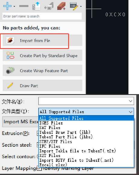
1. Click Import from File on the left side.
Click the drop-down triangle of File Type, and you can see the part formats supported for import in the current version.
For a detailed introduction to each format and the version of TubesT from which each format is supported, please refer to Detailed Explanation of Tube-Type File Formats.?
2. Set the parameters based on the types of the part.
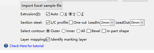
(1) Extrusion
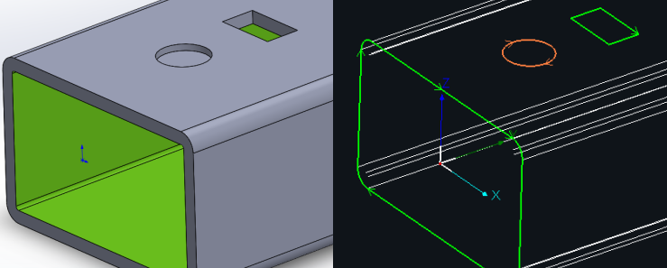
Auto Identify: The system will read the extrusion direction of the part automatically.
X, Y, Z: Adjust the extrusion direction manually. If the preview on the right side is not consistent with the actual situation, you can adjust the direction to make sure the preview is consistent with the part.
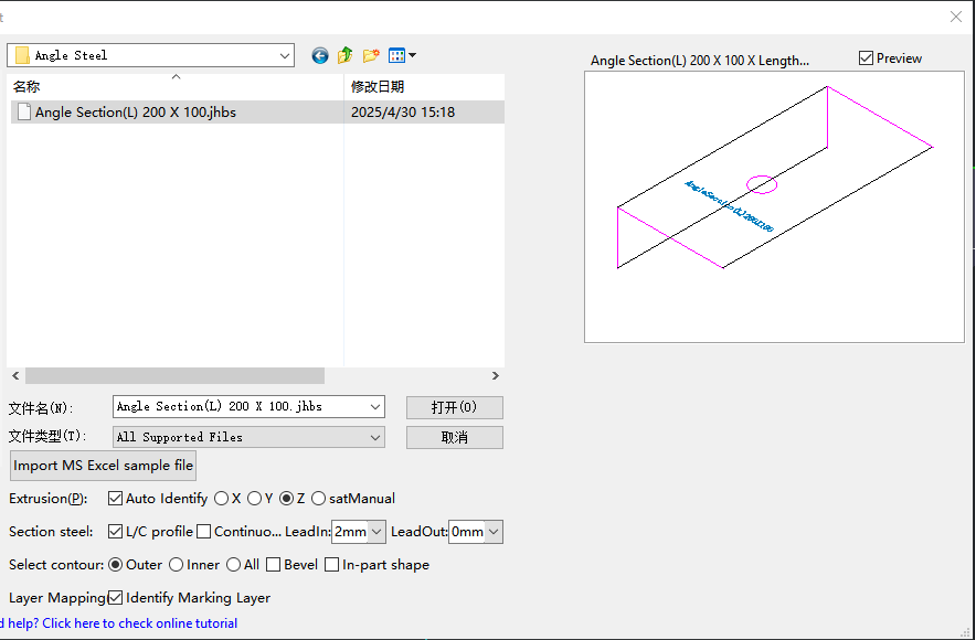
(2)Preview Information
Loading: The part file is loading. If the dimension information is shown as 0.00x0.00x0.0, then the part file is not read. You should adjust the parameters for debugging.
Part Dimension: The dimension will be shown on the top right corner of the window.
(3) Section Steel
If the imported part is channel steel, angle steel, or C-shaped steel, you shall check L/C profile. You may refer to Special Toolpath for details.
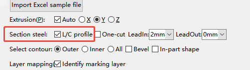
One-cut: For channel or angle steels, there are two cutting strategies—face-by-face cutting?(default) and?one-cut.
-
-
-
-
When unchecked, the system performs?face-by-face cutting, processing each face separately.
-
When checked, the system performs?single-cut, cutting the end contour of the part in one continuous pass.
-
-
-
LeadIn: The length of the lead-in line outside the tube when the special toolpath is automatically generated.
LeadOut: The length of the lead-out line outside the tube when the special toolpath is automatically generated.
Notice: All the default lead length of the special toolpath added to TubesT through Import from File and Draw Part shall be consistent with the value here !!
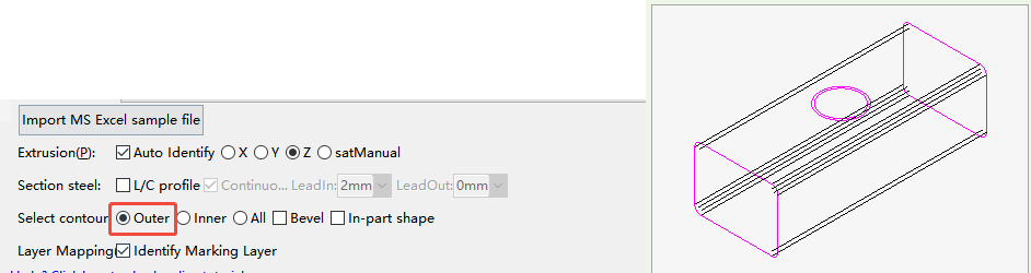
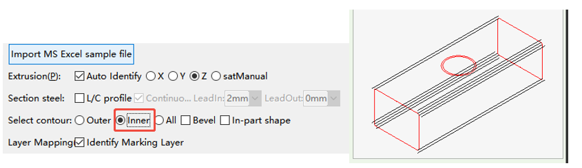
(4) Select contour
The actual tubes and parts have both outer contour and inner contour lines, but only one of them is needed for the processing. The Outer contour is generally selected.
?
(5) Bevel
If the part requires bevel cutting, check Bevel, and the bevel toolpath will be generated according to the drawing. You may refer to How to enable Bevel for details.
Notice: Only the equipment with a bevel cutting head can process the bevel. Please do not check the option for ordinary tube cutting machines.
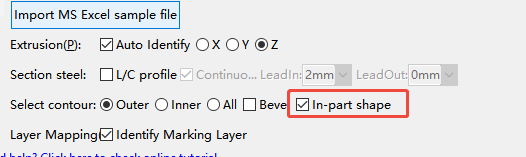
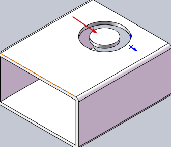
(6) In-part shape
In-part shape allows users to add parts from the cut-off material of the tube. Check In-part shape, and the system will recognize this part correctly.
Example: How to add In-part shape in Tubest.
(7)Layer Mapping
Check Identify Marking Layer, and the system can automatically distinguish between the through-cut and non-through-cut layer after importing. You may refer to Layer Mapping for details.
Ⅲ. FAQS
1.What should I do when the part failed for importing?
Please refer to How to Resolve Part Import Failed or Recognition Errors.
2.How to use Import MS Excel sample file??
Please refer to Batch Import Parts by Excel Table.
-
-
-
-
-
When unchecked, the system performs?face-by-face cutting, processing each face separately.
-
When checked, the system performs?single-cut, cutting the end contour of the part in one continuous pass.
-
-
-
TubesT - Import from File 5947viewⅠ. Overview
??II. Function Description
1. Click Import from File on the left side.
Click the drop-down triangle of File Type, and you can see the part formats supported for import in the current version.
For a detailed introduction to each format and the version of TubesT from which each format is supported, please refer to Detailed Explanation of Tube-Type File Formats.?
2. Set the parameters based on the types of the part.
(1) Extrusion
Auto Identify: The system will read the extrusion direction of the part automatically.
X, Y, Z: Adjust the extrusion direction manually. If the preview on the right side is not consistent with the actual situation, you can adjust the direction to make sure the preview is consistent with the part.
(2)Preview Information
Loading: The part file is loading. If the dimension information is shown as 0.00x0.00x0.0, then the part file is not read. You should adjust the parameters for debugging.
Part Dimension: The dimension will be shown on the top right corner of the window.
(3) Section Steel
If the imported part is channel steel, angle steel, or C-shaped steel, you shall check L/C profile. You may refer to Special Toolpath for details.
One-cut: For channel or angle steels, there are two cutting strategies—face-by-face cutting?(default) and?one-cut.
LeadIn: The length of the lead-in line outside the tube when the special toolpath is automatically generated.
LeadOut: The length of the lead-out line outside the tube when the special toolpath is automatically generated.
Notice: All the default lead length of the special toolpath added to TubesT through Import from File and Draw Part shall be consistent with the value here !!
(4) Select contour
The actual tubes and parts have both outer contour and inner contour lines, but only one of them is needed for the processing. The Outer contour is generally selected.
?
(5) Bevel
If the part requires bevel cutting, check Bevel, and the bevel toolpath will be generated according to the drawing. You may refer to How to enable Bevel for details.
Notice: Only the equipment with a bevel cutting head can process the bevel. Please do not check the option for ordinary tube cutting machines.
(6) In-part shape
In-part shape allows users to add parts from the cut-off material of the tube. Check In-part shape, and the system will recognize this part correctly.
Example: How to add In-part shape in Tubest.
(7)Layer Mapping
Check Identify Marking Layer, and the system can automatically distinguish between the through-cut and non-through-cut layer after importing. You may refer to Layer Mapping for details.
Ⅲ. FAQS
1.What should I do when the part failed for importing?
Please refer to How to Resolve Part Import Failed or Recognition Errors.
2.How to use Import MS Excel sample file??
Please refer to Batch Import Parts by Excel Table.

